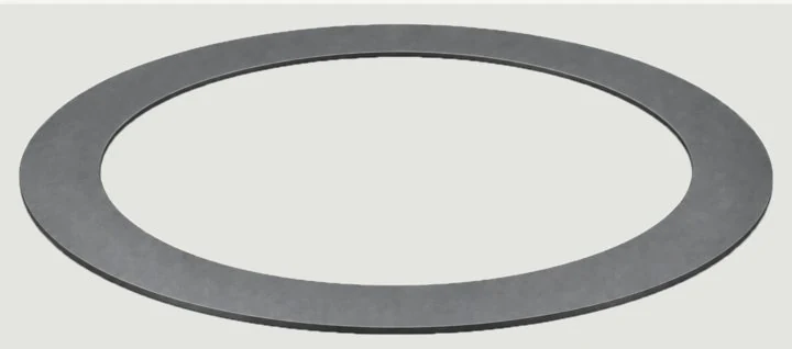
Focus-ring machining connects supporting faces, inner/outer contours, steps and mating relationships. Translate material and thin-wall support conditions into datums and rough/finish sequencing, then coordinate lapping, polishing or applicable surface treatment and inspect the resulting geometry, edges and cleanliness. Suitable conductive materials may use an EDM branch; wheel preparation and dressing support grinding.
Translate drawing requirements into process targets.
Drawing requirement examples
Use these examples to define selection and validation criteria. Confirm actual targets against the customer drawing, material and inspection method.
Inner-to-outer concentricity
≤0.05 mm
Base-face flatness
≤50 μm
Height tolerance
±0.1 mm
Groove-depth tolerance
±0.05 mm
Surface roughness
Ra ≤0.8 μm
Inputs for the process solution
Material & grade
Provide the material grade, forming or coating condition, and actual conductivity for any proposed EDM operation.
Ring dimensions & geometry
Specify inner and outer diameters, wall thickness, height, steps, holes and grooves.
Geometry & mating requirements
Define concentricity relationships, faces, mating dimensions and inspection datums.
Edge & surface requirements
State edge-integrity, surface-roughness and subsequent-treatment requirements.
Workholding & production conditions
Provide the current workholding, setup-change method, allowance, batch size and target cycle time.
MACHINING CHALLENGES
Identify the challenge. Define the process control.
01
Relate thin-wall support to released-part geometry
Coordinate support, clamping and reversal with the measurement condition. Inspect geometry in the fixture and after release separately rather than recording only an in-setup acceptance result.
02
Use common datums for contours, faces and steps
Features completed in multiple setups need a traceable datum chain. Define support, location and reversal transfers first, then inspect mating relationships and remaining allowance at each operation.
03
Validate the route for each actual material
Silicon, SiC and quartz differ in material and incoming condition. Validate removal method, machining direction, edges and surfaces for each grade; the SiC name alone does not establish EDM suitability.
04
Link profile-wheel condition to the machined feature
Wheel-profile changes must be considered when assessing mating features. Link wheel specification, profile inspection and dressing conditions to part measurements, then recheck an agreed feature after dressing before continuing grinding.
05
Recheck geometry and edges after surface treatment
Coordinate subsequent lapping, polishing or chemical treatment with earlier allowance and mating requirements. Record geometry, surfaces and edges before and after finishing; accept the part in its final treated condition.
Within confirmed support and access limits, remove material from contours and steps in stages, retaining agreed allowance for finish grinding and subsequent surface treatment.
Purpose
Separate bulk removal from final mating geometry so finish grinding starts with defined allowance and datums.
Operation output
A rough-machined ring with traceable allowance and geometry
Inspection items
Inspect rough contours, wall thickness, edges and allowance for finish grinding.
Handover conditions
Transfer rough-grinding results, released geometry, finishing allowance and checked wheel condition.
For the actual material and component specification, coordinate the customer’s or supporting lapping, CMP polishing or suitable chemical treatment, aligning the preceding profiles with subsequent surface requirements.
Select the treatment and sequence through the actual material, surface requirements and process validation.
Purpose
Carry completed geometry, mating and edge conditions into finishing alongside the surface requirements.
Operation output
Ring surfaces meeting requirements for cleaning and final inspection
Inspection items
Inspect surfaces, edges and post-treatment geometric changes using the agreed methods.
Handover conditions
Transfer pre-/post-finishing inspection, allowed removal, applicable treatment conditions and cleaning requirements.
06
Customer / supporting process interface
Cleaning & controlled handling
Complete supporting cleaning, drying and handling against customer procedures before subsequent assembly or application testing.
Purpose
Establish agreed cleaning and handling conditions before final geometry and application acceptance.
Operation output
A cleaned ring handled according to customer procedures
Inspection items
Check cleanliness, appearance, identification and handling records.
Handover conditions
Transfer cleaning batch, visual/cleanliness inspection, drying and packaging/handling records.
07
Customer / supporting process interface
Geometric & application acceptance
Link operation dimensional records with customer application requirements, completing geometric and application acceptance separately.
Purpose
Check geometry, fits and customer application requirements on the finally treated part.
Operation output
Ring acceptance records traceable to the manufacturing operations
Inspection items
Inspect mating and geometric requirements against the drawing, and complete application tests against customer specifications.
Handover conditions
Transfer material, process, final-geometry and applicable application-test records under one part identifier.
FEATURE-SPECIFIC ROUTES
Additional operations selected for the material and geometry
Conditional route 01
Contour/cavity pre-machining branch for conductive grades
For an actual grade with adequate conductivity evidence, select NH400PV wire EDM or NH430D die-sinking EDM for a specified contour or cavity. Use it as pre-machining or an alternative operation for that feature, retaining allowance for subsequent grinding/treatment; it does not replace final grinding.
The grade must have suitable conductivity, and geometry, workholding and process must be validated with a sample.
Use EDM as an alternative/supplementary route for a specified contour or cavity, retaining interfaces for later grinding or surface treatment.
Operation output
The specified profile or cavity produced through the selected EDM route
Inspection items
Inspect the operation’s profile, dimensions, surface and allowance for subsequent treatment.
Handover conditions
Transfer conductivity evidence, selected route, feature inspection and downstream allowance; do not apply this branch to insulating grades.
GRINDING SUPPORT
Wheel production and dressing support component grinding.
Profiled-wheel production & dressing
Where component grinding uses suitable electrically conductive metal-bond diamond or CBN profiled wheels, assess the SL25L / SL30 for wheel-profile production, dressing and worn-profile restoration. This supporting operation acts on the wheel and is coordinated separately with component grinding and measurement results.
For suitably conductive materials, assess die-sinking and profile wire cutting separately, confirming the geometry and accessible scope through samples.
VALIDATION & HANDOVER
Connect the process chain through inspection and handover records.
Validation item
Inspection method
Handover record
Material & conditional route
Use actual grade, incoming condition and required conductivity evidence to allocate mechanical/EDM operations.
Material batch, conductivity evidence and selected-route confirmation.
Support, reversal & released condition
Inspect datums and ring geometry in agreed support, clamping, reversal and release conditions.
Workholding arrangement, datum transfers and condition-specific measurement records.
Contours, steps & fits
Relate contour, face and step measurements to a common drawing-datum chain.
Feature dimensions, location/fit relationships, edges and remaining allowance.
Wheel & dressing loop
Relate wheel profile and dressing conditions to remeasurement of a representative feature after dressing.
Wheel identification, profile/dressing records and part remeasurement results.
Post-finishing & whole-part acceptance
Inspect surfaces, geometry, cleanliness and applicable customer requirements in the final treated condition.
Pre-/post-finishing comparison and final whole-part acceptance records.
Prepare these inputs for the process discussion
Actual material grade, forming/coating condition and available electrical information.
Complete drawings for ring envelope, wall thickness, faces, steps and fits.
Incoming/stage allowances, support/clamping and reversal-datum arrangement.
Wheel specification, applicable bond, current profile and existing dressing/inspection records.
Subsequent finishing, cleaning and application-acceptance conditions, plus output and implementation objectives.
VALIDATE YOUR MACHINE SELECTION
Bring the drawing. Define the machine solution.
Share the part, material, critical requirements and output objectives to discuss candidate machines, trials and configuration.
An account manager responds within 24 hours. Trials generally take 3–20 days; an NDA is available.
 北京凝华科技有限公司