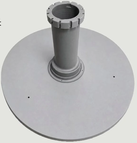
Aluminum nitride heaters process and equipment solution
Aluminum-nitride heater machining combines plate/shaft geometry, embedded-structure protection, thermocouple holes and lead passages. Coordinate rough/finish grinding, dedicated hole making, local grooves and surface finishing within the permitted removal allowance, recording machining results separately from customer-specified heating, insulation and other functional acceptance.
Translate drawing requirements into process targets.
Drawing requirement examples
Use these examples to define selection and validation criteria. Confirm actual targets against the customer drawing, material and inspection method.
Flatness (standard / higher-demand examples)
≤50 μm / ≤30 μm
Parallelism
≤20 μm
External roundness
≤0.02 mm
Thermocouple-hole straightness
≤0.05 mm
Thermocouple hole-bottom position
≤0.2 mm
Shaft coaxiality
≤0.05 mm
Inputs for the process solution
Material & formed condition
Provide the AlN grade, as-sintered or joined geometry and machining allowance.
Plate surfaces & geometry
Define flatness, parallelism, thickness, external geometry and inspection datums.
Embedded & protected areas
Within the permitted disclosure scope, identify embedded features, protective layers and no-removal areas.
Connections & holes
Provide the plate-to-shaft relationship, connections, and hole or groove sizes, depths and positions.
Production & inspection plan
State target output, process datums, inspection methods and subsequent surface requirements.
MACHINING CHALLENGES
Identify the challenge. Define the process control.
01
Balance plate correction and embedded-structure protection
Rough grinding, finish grinding and later finishing all consume the removal allowance. Obtain customer-disclosable embedded-structure information and protection boundaries, then document face allowances, no-machining regions and reinspection points.
02
Coordinate plate, shaft and connecting datums
Separate location schemes for the plate, shaft and connecting structures can make reversal and assembly relationships difficult to trace. Use drawing datums to coordinate machining order and inspection positions, recording support and clamping conditions.
03
Control thermocouple-hole location, depth and bottom position
Deep holes require checks beyond diameter: entry direction, straightness relationships, effective depth and bottom position. Confirm equipment scope and inspection method for dedicated hole making separately from structural grinding; travel alone does not establish suitability.
04
Coordinate lead grooves and protected regions
Local grooves or surface features must be checked against embedded regions, passages and later finishing. Validate laser depth, edges and subsequent treatment on the actual material and a representative feature before fixing the operation sequence.
05
Separate machining acceptance from heater function
Dimensional and surface acceptance does not replace the customer’s heating, insulation or other functional assessment. Link machining, cleaning/handling and functional acceptance to the same part, defining each process handover responsibility.
COMPLETE PROCESS CHAIN
From incoming part to final acceptance.
Incoming part & protected regions → plate/datum grinding → connecting features → thermocouple holes/lead passages → local laser features → surface finishing → cleaning & geometric/functional acceptance
NINVA machine operationsCustomer / supporting process interfaces
Grind suitable connections, mating features, holes and grooves against plate-to-shaft relationships, opening directions and tool space, using the preceding datums.
The actual material, geometry, workholding and tool access must be validated.
Purpose
Use the established datums for accessible structural features, giving dedicated holes and local grooves defined location and access.
Operation output
Connections and mating structures with the agreed mechanical features machined
Inspection items
Inspect connection datums, feature dimensions, positions and edge condition.
Handover conditions
Transfer plate/shaft or connecting datums, structural dimensions, remaining allowance and hole/groove access directions.
Coordinate customer or supporting dedicated hole-making processes for specified thermocouple holes, lead holes or passages. Check entry direction, depth, bottom position and protected regions; local laser engraving does not establish deep-hole capability.
Purpose
Perform hole making within established datums and protection boundaries, coordinating sequence with local grooves and finishing.
Operation output
Hole/passage features with datum and protected-region records
Inspection items
Inspect diameter, position, depth, bottom, entry and relationship to protected regions.
Handover conditions
Transfer hole identifiers, machining direction, actual inspection method and bottom/protection-boundary verification.
05
Customer / supporting process interface
Coordinate lapping, polishing & CMP
Coordinate the customer’s or supporting operations’ lapping, polishing or CMP against heater working-surface and protected-area requirements, controlling allowable removal during subsequent finishing.
Confirm finishing methods and stock against the material, embedded-feature protection and customer process.
Purpose
Constrain later removal against completed holes/grooves, protected regions and functional faces so finishing remains consistent with whole-part requirements.
Operation output
Surfaces meeting the requirements for subsequent cleaning and inspection
Inspection items
Inspect geometry, roughness and the treated surface condition against the drawing.
Handover conditions
Transfer pre-/post-finishing geometry/surface inspection, removal records and cleaning requirements.
06
Customer / supporting process interface
Cleaning & transfer to assembly
Coordinate cleaning, drying, packaging or transfer to subsequent assembly against customer requirements, maintaining traceable process records.
Purpose
Cleaning, drying and handling establish the agreed handover condition for assembly and functional testing.
Operation output
A component ready for subsequent assembly or functional testing
Inspection items
Check cleanliness, appearance, identification and handling conditions.
Handover conditions
Transfer cleaning batch, visual/cleanliness inspection, identification and assembly-handling requirements.
07
Customer / supporting process interface
Geometric & heater-function acceptance
Coordinate mechanical dimensional inspection with the customer’s heater-function tests, defining each operation’s output and acceptance responsibility.
Purpose
Check machining results and customer functional items separately rather than using one dimension as whole-heater acceptance.
Operation output
Acceptance records with geometry and function confirmed separately
Inspection items
Complete the applicable checks against the component drawing and heater functional specification.
Handover conditions
Transfer geometry, surface and applicable functional-test records linked to drawing revision and part identifier.
FEATURE-SPECIFIC ROUTES
Additional operations selected for the material and geometry
Conditional route 01
Laser-machine local surface features
Assess the LTC400 for local engraving, grooves or cutting in suitable AlN, coordinating the machining area with embedded-feature protection and subsequent surface requirements.
The drawing must contain laser-suitable local features, with material and protection conditions confirmed.
Validate local laser features separately from dedicated deep holes, using protection boundaries to place the operation before or after finishing.
Operation output
The specified local surface features
Inspection items
Inspect local dimensions, depth, edges and their relationship to protected areas.
Handover conditions
Transfer local feature dimensions, depth, edges and protection-boundary verification.
GRINDING SUPPORT
Wheel production and dressing support component grinding.
Profiled-wheel production & dressing
Where component grinding uses suitable electrically conductive metal-bond diamond or CBN profiled wheels, assess the SL25L / SL30 for wheel-profile production, dressing and worn-profile restoration. This supporting operation acts on the wheel and is coordinated separately with component grinding and measurement results.