NINVA 凝华北京凝华科技有限公司

SHOWERHEAD

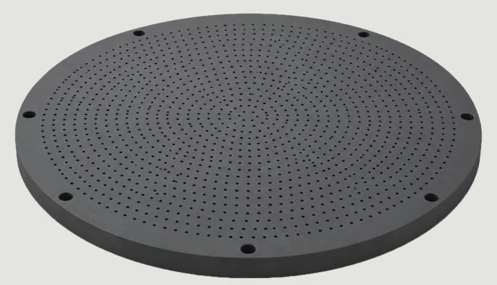
Showerheads process and equipment solution

Showerhead manufacture coordinates plate geometry, hole patterns and gas-distribution features through common datums, opening quality and hole-to-hole consistency. Connect plate/structural machining, dedicated hole making, required finishing and cleaning/inspection into a traceable route. NINVA equipment covers validated grinding and suitable local laser or conductive-material EDM operations; define dedicated deep-microhole, cleaning and flow/other application-test interfaces separately.

Silicon carbide · SiCAlumina · Al₂O₃Quartz
Explore all part solutions
Showerheads

DRAWING REQUIREMENTS

Translate drawing requirements into process targets.

Drawing requirement examples

Use these examples to define selection and validation criteria. Confirm actual targets against the customer drawing, material and inspection method.

Hole-diameter tolerance
±0.03 mm
Hole-position tolerance
±0.05 mm
Depth-to-diameter ratio
10–50
Flatness (standard / higher-demand examples)
≤80 μm / ≤50 μm

Inputs for the process solution

Material & surface condition
Provide the grade, forming method, coating and surface condition. For EDM assessment, include evidence of suitable conductivity.
Complete hole specification
Specify diameters, depths, quantity, pitch, stepped geometry and opening direction.
Hole-edge & bore requirements
Define edge chipping, burr or redeposition limits, bore requirements and subsequent treatment.
Plate surfaces & datums
Provide plate geometry, thickness, hole locations, locating datums and the workholding arrangement.
Consistency & production targets
State sampling or individual-hole inspection methods, target cycle time, batch size and the current bottleneck.

MACHINING CHALLENGES

Identify the challenge. Define the process control.

01

Select the route from diameter, depth and hole geometry

Do not select microhole equipment from diameter alone. Provide depth, aspect relationship, through/blind geometry, entrance/exit and material condition together; confirm access and inspection separately for dedicated hole making.

02

Keep hole-pattern location consistent with plate datums

Plate grinding, contour work and hole making need one traceable datum chain. Define locating faces and reversal before hole making so positional results remain related to plate and assembly requirements.

03

Relate repeated-hole consistency to tool/process condition

Record opening condition, position, internal surface and machining order during repeated-hole work. Set project-agreed process checks and link hole identifiers/results to tool condition or process adjustments.

04

Coordinate hole edges with later finishing

Coordinate opening and thin-edge requirements across hole making, steps/contours and finishing. Inspect entrance and exit separately and define areas affected by finishing and opening-protection requirements rather than accepting only one face.

05

Connect internal cleanliness, patency and application testing

After hole machining, verify internal cleanliness, patency and applicable gas-distribution or flow items to the customer specification. Link hole identifiers, cleaning batch and application tests; plate dimensions do not replace hole-pattern acceptance.

COMPLETE PROCESS CHAIN

From incoming part to final acceptance.

Blank & datums → plate/contour grinding → dedicated hole-pattern machining → conditional local-feature branches → surface finishing → cleaning/patency checks → hole-pattern & application acceptance

NINVA machine operationsCustomer / supporting process interfaces
  1. 01Prepare the blank & retain datum stock
  2. 02Grind datum & plate surfaces
  3. 03Grind profiles & stepped features
  4. 04Machine holes & perform in-process checks
  5. 05Surface finishing, cleaning & patency checks
  6. 06Hole geometry & application inspection
  1. 01
    Customer / supporting process interface

    Prepare the blank & retain datum stock

    Allocate plate, profile and hole-operation stock against the material, formed condition or coating state.

    Purpose
    Establish common material, incoming-condition and plate/hole allowances so downstream routes do not consume allowance independently.
    Operation output
    A plate blank and stock record for subsequent operations
    Inspection items
    Check material, incoming envelope, surface condition and stock for each operation.
    Handover conditions
    Transfer material batch, blank/coating condition, drawing revision, plate dimensions and face/hole-region allowances.
  2. 02
    Operation supported by NINVA equipment

    Grind datum & plate surfaces

    Assess NHM-series grinding against plate surfaces, location and clamping to establish datums for profile and hole operations.

    Purpose
    Create plate and locating datums before hole making so positions can be related to assembly requirements.
    Operation output
    Plate surfaces and locating datums for profile and hole operations
    Inspection items
    Inspect plate geometry, thickness, datum relationships and remaining stock.
    Handover conditions
    Transfer plate, thickness, locating-face, reversal-relationship and inspection-condition records.
  3. 03
    Operation supported by NINVA equipment

    Grind profiles & stepped features

    Grind suitable ceramic external profiles, steps and accessible structures from the preceding datums.

    Material, tooling and workholding space must be suitable for the selected model.

    Purpose
    Connect outer/stepped features to the plate datums, defining boundaries for hole-making workholding and tool paths.
    Operation output
    Profiles and stepped features related to the hole-pattern location
    Inspection items
    Inspect feature dimensions, locations, edges and the accessible range after workholding.
    Handover conditions
    Transfer contours, steps, hole-region location, edge inspection and locating faces for dedicated hole making.
  4. 04
    Customer / supporting process interface

    Machine holes & perform in-process checks

    Coordinate the customer’s existing or supporting hole-making operations against diameter, depth, hole type and material. Ultrasonic drilling, or ultrasonic finishing after laser pre-drilling, may be assessed as supporting routes, with hole edges, bores and consistency across repeated holes validated separately.

    Assess ultrasonic and other supporting routes against the actual equipment, material and hole type.

    Purpose
    Validate dedicated hole-making routes separately, then link hole identifiers and process checks to finishing/cleaning.
    Operation output
    A hole pattern produced and recorded using the agreed method
    Inspection items
    Inspect diameters, locations, depths, edges and bores, with inspection quantity and sampling defined for the project.
    Handover conditions
    Transfer the hole map, machining order, tool/process condition, opening/internal-surface inspection and areas requiring cleaning.

  5. 05
    Customer / supporting process interface

    Surface finishing, cleaning & patency checks

    Coordinate customer or supporting lapping/CMP, cleaning and drying against plate, opening and internal-surface requirements. Identify hole regions requiring cleaning or protection, and confirm patency and subsequent application-test conditions to the project specification.

    Confirm finishing and cleaning methods and their sequence against material, hole geometry and customer specifications.

    Purpose
    Include finishing effects on openings and plate surfaces in pre-cleaning inspection, preserving the condition needed for application acceptance.
    Operation output
    Plate surfaces and holes meeting the requirements for subsequent application inspection
    Inspection items
    Check cleanliness, surfaces and hole-edge integrity against customer specifications.
    Handover conditions
    Transfer pre-/post-finishing surface/opening records, cleaning batch and patency-check arrangements.
  6. 06
    Customer / supporting process interface

    Hole geometry & application inspection

    Link hole-machining records with geometric, flow or other applicable tests defined by the drawing and customer application specifications.

    Purpose
    Assess hole geometry and applicable functional requirements under the same hole map and drawing revision.
    Operation output
    Traceable hole-pattern and application inspection records
    Inspection items
    Confirm hole geometry, consistency and the application acceptance items agreed for the project.
    Handover conditions
    Transfer complete dimension/position, opening/internal-surface, cleanliness/patency and agreed application-test records.

FEATURE-SPECIFIC ROUTES

Additional operations selected for the material and geometry

Conditional route 01

Local laser-shaping & cutting branch

Assess the LTC400 for local features in suitable ceramics, validating laser processing and subsequent surface requirements for the actual hole type or profile.

The actual material, feature depth and access must be suitable for a machining trial; deep microholes require separate validation.

Purpose
Treat local laser machining as a conditional route for specified features, not automatic coverage of all deep microholes and acceptance items.
Operation output
A local laser-machined feature validated for the specific geometry
Inspection items
Inspect local dimensions, hole or cut edges, surface condition and subsequent-treatment allowance.
Handover conditions
Transfer validated feature dimensions, edges, post-treatment allowance and interfaces with the main hole-pattern route.
Conditional route 02

Additional EDM branch for conductive materials

For suitably conductive grades, assess NH400PV wire cutting or NH430D die-sinking against profile or cavity requirements, separately from the hole-making operation.

Conductivity, actual geometry and process must be validated using the specific grade and a sample.

Purpose
Conductive-material contours or cavities may use an EDM branch; the hole-pattern operation still needs separate confirmation.
Operation output
An EDM-machined profile or cavity within the validated scope
Inspection items
Inspect the feature’s dimensions, surface and datum relationships, recording subsequent-treatment requirements.
Handover conditions
Transfer actual conductivity evidence, specified contour/cavity records and downstream grinding/finishing requirements.

GRINDING SUPPORT

Wheel production and dressing support component grinding.

Profiled-wheel production & dressing

Where component grinding uses suitable electrically conductive metal-bond diamond or CBN profiled wheels, assess the SL25L / SL30 for wheel-profile production, dressing and worn-profile restoration. This supporting operation acts on the wheel and is coordinated separately with component grinding and measurement results.

EQUIPMENT COMBINATIONS

Combine equipment around the machining task.

01

Plate/structural grinding with dedicated hole-making interfaces

For plate/contour work and hole datums coordinated with the customer’s existing hole-making line.

NINVA equipment and roles

Component grinding: establish plate, locating and structural datums for hole making and machine validated accessible features.

Wheel support: prepare and dress profiles when suitable metal-bond profiled wheels are used.

Customer and supporting operations

  • Specify dedicated microhole equipment/processes, lapping/CMP, cleaning and hole-pattern application tests separately.

Combination validation priorities

  • Validate common plate/hole datums, fixture space, hole-region access and handover allowance.
  • Link tool condition, hole identifiers, process checks and cleaning batches.
02

Grinding with a local laser-feature branch

For specified local shaping, cutting or surface features to be confirmed by machining trials.

NINVA equipment and roles

Create plate, contour and locating datums related to the hole pattern.

Local branch: establish laser coverage against actual material, thickness, hole/contour geometry and edge requirements.

Customer and supporting operations

  • Plan high-aspect-ratio holes and internal finishing as dedicated operations; other LTC400 samples do not establish those capabilities.
  • Define finishing, opening cleanup, cleaning and application-test interfaces separately.

Combination validation priorities

  • Validate dimensions, edges, surfaces and downstream allowance on the actual hole geometry or local feature.
  • Define the laser/dedicated-hole sequence and common location references.
03

Conductive-material contour/cavity branch

For confirmed conductive material and a specified contour or cavity.

NINVA equipment and roles

Conditional branch: die-sinking for cavities or wire EDM for contours, selecting the appropriate model for the feature.

Coordinate plate/datum and subsequent suitable structural grinding.

Customer and supporting operations

  • Confirm the dedicated microhole route, finishing, cleaning and application acceptance separately; the EDM branch does not automatically cover them.

Combination validation priorities

  • Record conductivity evidence, machining regions and allowance retained after EDM.
  • Validate contour/cavity and hole-pattern results separately and confirm their datum handover.
View the function and conditions of each machine type

Covers validated plate, datum and structural grinding. Confirm dedicated deep-microhole operations separately; plate-grinding capability does not establish hole-making capability.

For assessing local laser shaping and cutting of suitable ceramics, with the operation confirmed against the actual hole type and subsequent requirements.

Additional routes for suitably conductive grades: assess die-sinking and profile wire cutting separately against geometry and conductivity.

VALIDATION & HANDOVER

Connect the process chain through inspection and handover records.

Validation itemInspection methodHandover record
Plate & hole-pattern datumsCoordinate drawing datums and reversal relationships across plate, contours, locating features and hole pattern.Datum transfers, workholding condition, plate/thickness and hole-region location records.
Hole geometry & openingsInspect dimensions, position, depth and entrance/exit requirements by hole identifier, with project-agreed coverage.Hole map, actual dimensions, opening/internal-surface condition and inspection method.
Repeated-hole processCompare machining order and results before/after tool or process changes at agreed process-check points.Hole identifiers, tool/process condition, adjustments and in-process inspection records.
Finishing & cleaning handoverCheck finishing-affected regions, opening protection and post-cleaning patency/cleanliness requirements.Pre-/post-finishing, cleaning-batch, patency and cleanliness records.
Application itemsWhere the drawing specifies flow, gas distribution or other items, the customer or agreed supporting party tests them by the applicable method.Application-test results linked to the hole map and part identifier.

Prepare these inputs for the process discussion

  1. Material grade, plate diameter/thickness, forming/coating condition and incoming allowance.
  2. Complete identified hole map, with diameter, depth, geometry and entrance/exit requirements.
  3. Datums and workholding for plate, contours, steps and hole pattern.
  4. Current hole-making route, tool condition, typical defects, cycle time and process-inspection records.
  5. Subsequent finishing, cleaning/patency, flow/other application-test methods and production objectives.

VALIDATE YOUR MACHINE SELECTION

Bring the drawing. Define the machine solution.

Share the part, material, critical requirements and output objectives to discuss candidate machines, trials and configuration.

An account manager responds within 24 hours. Trials generally take 3–20 days; an NDA is available.